Opto Reflective Sensor Project Pdf

Https Encrypted Tbn0 Gstatic Com Images Q Tbn 3aand9gcq00tgg22fawuxj8u 3etdxa Yqu7k By5zag Usqp Cau
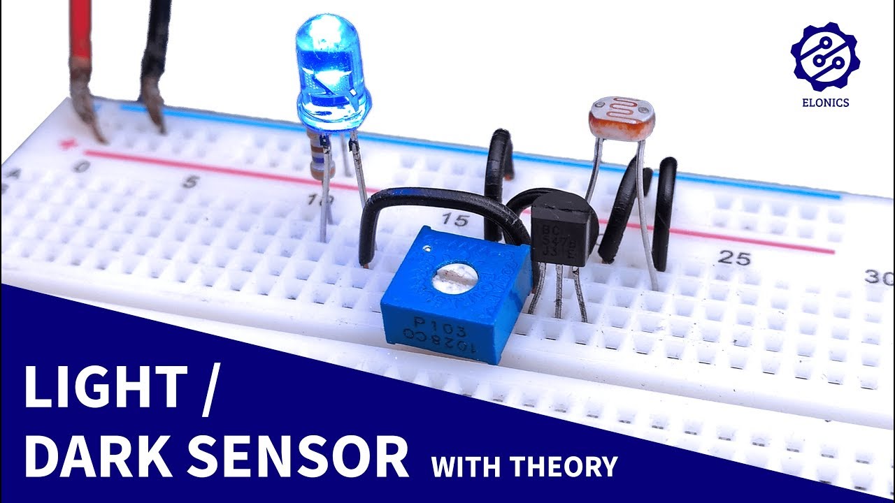
Light Sensor Circuit On Breadboard Darkness Detector Ldr Transistor Projects Youtube
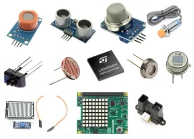
Sensor Based Projects For Final Year Engineering Students
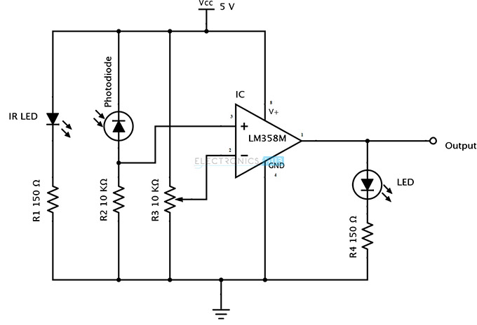
Ir Infrared Obstacle Detection Sensor Circuit
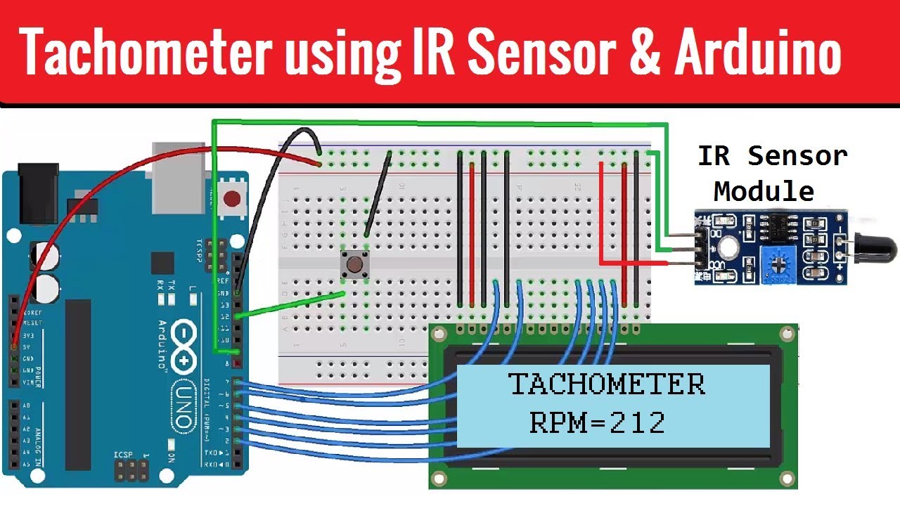
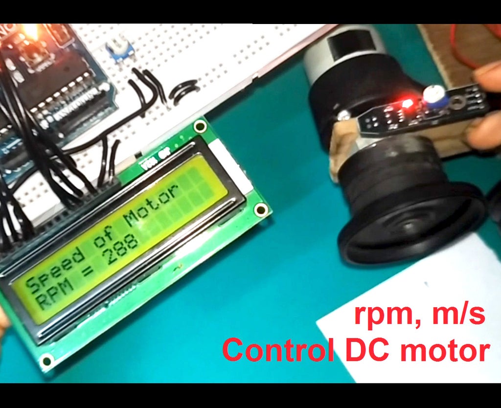
Tachometer Rpm Measurement Using Ir Sensor Arduino Youtube
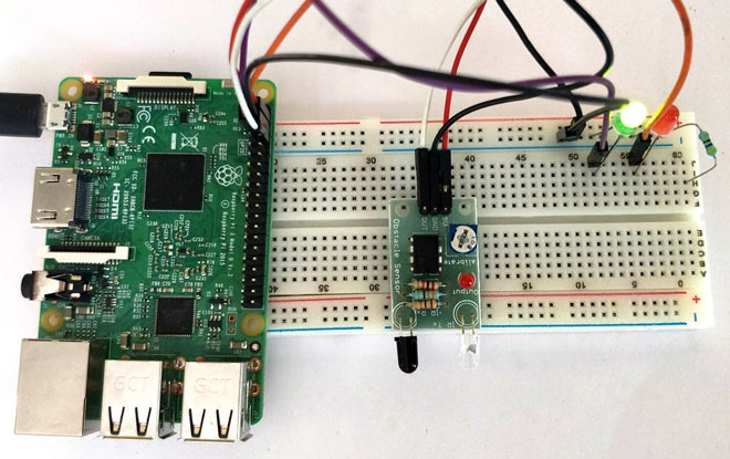
Raspberry Pi Infrared Ir Sensor Interfacing Tutorial
6 346 2 71000 cut tape ct alternate packaging not for new designs 19 7 50cm 1 6 reflective non metallic surface mount 400ma.
Opto reflective sensor project pdf.

Different Types Of Sensors With Applications Introduction To Sensors The World Is Full Of Sensors I Sensor Arduino Light Sensor

Cheap Sensors Rpr220 6 Steps Instructables

Ir Detector Project Ir Sensor Photo Diode Circuit Easy Electronic Youtube

Fan Speed Measurement Using Ir Sensor Arduino
How To Use A Lm393 Ir Speed Sensor With An Arduino Tutorial Youtube

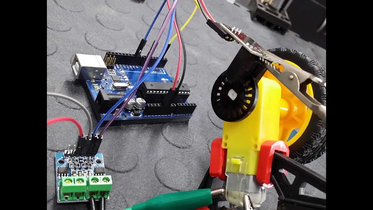
Control A Stepper Motor With Hall Effect Switches Youtube

Simple Ldr Circuit Diagram Ldr Circuit Ldr Ldr Light
Http Medcraveonline Com Ijbsbe Ijbsbe 04 00097 Pdf
Different Types Of Optical Sensors And Applications

Irobobumper Project Mouser
What Is A Photoelectric Sensor Sensor Basics Introductory Guide To Sensors Keyence

Optoelectronic Sensor An Overview Sciencedirect Topics
Phototransistor Circuit Diagram Construction And Its Appplications

Infrared Sensor Library For Proteus The Engineering Projects
Optocouplers Working Characteristics Interfacing Application Circuits Homemade Circuit Projects
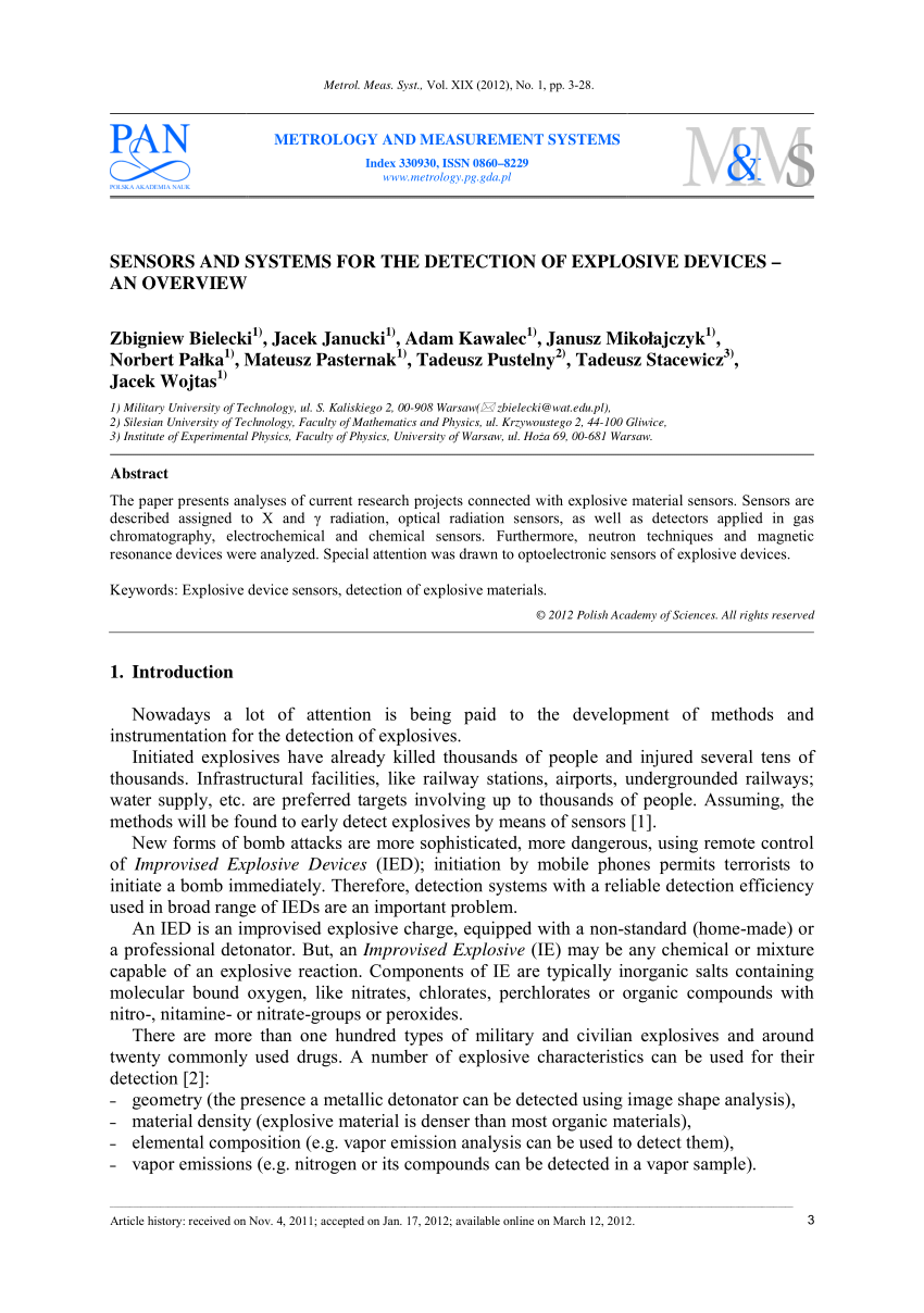
Pdf Sensors And Systems For The Detection Of Explosive Devices An Overview
Motor Speed Tester Using Arduino Ir Sensor 6 Steps Instructables
Https Web Mit Edu 6 101 Www S2018 Projects Gravesjo Project Final Report Pdf
Https Encrypted Tbn0 Gstatic Com Images Q Tbn 3aand9gctpfv4n Kzpbxubiasqdhz4x2sp Ul66jasbm4oif4 Tarivnat Usqp Cau

Digital Tachometer Rpm Using Ir Sensor With Arduino
Sensors April 2017 Browse Articles

Build A Zippy Line Following Robot Bluebot Project 3 Science Project

Automatic Street Light Control Using Ldr Oled Semiconductors

All About Proximity Sensors Which Type To Use Latest Open Tech From Seeed Studio
Source : pinterest.com
